- info@inthings.tech
- Room No. 16/591 Karinkallathani, Chethalloor-PO, Thachanattukara-II Palakkad.

About Inthings
Inthings, founded in May 2019, is a dynamic and innovative technology company driven by a team of visionary entrepreneurs and highly skilled software engineers.
Customers & Affiliations
Case Study Details
Case Study Details
January 2026

Seamless Sensor Data Transmission With LoRa Strategic Optimizations
Objective:
“Enhancing LoRa Communication Range: Best Practices and Considerations”
Improving the range of a LoRa (Long Range) communication system involves optimizing several factors related to both hardware and environmental conditions. Here are some strategies to enhance LoRa range:
1. Antenna Optimization
· High-Gain Antennas: Use high-gain antennas on both the transmitter and receiver. Higher gain antennas focus the signal more effectively, extending the range.
· Antenna Placement: Position antennas at a higher elevation to reduce obstructions and improve line-of-sight communication.
· Antenna Orientation: Ensure the antennas are correctly oriented and matched for polarization (e.g., both vertical or both horizontal).
2. Transmission Power
· Increase Power Output: If regulations permit, increase the transmission power of the LoRa device. Most LoRa devices allow adjustments to the transmission power within legal limits.
3. Spreading Factor (SF) and Bandwidth
· Spreading Factor: Use a higher spreading factor. Higher spreading factors increase the sensitivity of the receiver but also increase the time on air.
· Bandwidth: Use a narrower bandwidth. Narrower bandwidths can improve range at the cost of data rate.
4. Data Rate and Coding Rate
· Lower Data Rate: Lower data rates generally improve range because they increase the time the signal is on air, improving the chances of successful reception.
· Coding Rate: Adjust the coding rate to add more redundancy to the transmitted data, improving robustness against interference and increasing range.
5. Environmental Factors
· Clear Line of Sight: Minimize obstructions between the transmitter and receiver. Buildings, trees, and other obstacles can significantly reduce range.
· Reduce Interference: Ensure that the operating frequency is free from interference from other sources. Using channels with less traffic can improve range.
6. Antenna Quality
· Quality Antennas: Use high-quality antennas with good efficiency and proper matching to the LoRa device.
· Cable Quality: Use high-quality, low-loss coaxial cables if external antennas are used to minimize signal loss.
7. LoRa Network Settings
· Adaptive Data Rate (ADR): Use ADR to allow the network to automatically optimize data rates and transmission parameters for each node.
· Diversity and Redundancy: Implement multiple gateways or use network diversity to ensure there is always a gateway within range of any given node.
8. LoRa Device Configuration
· Firmware Updates: Ensure that your LoRa devices have the latest firmware updates, which may include optimizations for range and performance.
· Proper Configuration: Verify that the devices are configured correctly for the intended application and environment.
9. Using Repeaters or Gateways
· Additional Gateways: Deploy additional gateways in strategic locations to cover areas where the signal might be weak.
· Repeaters: Use repeaters to extend the range by relaying signals between the transmitter and receiver.
10. Environmental Adaptations
· Weather Considerations: Be aware that weather conditions like rain, fog, and snow can affect the range. Plan deployments accordingly.
· Rural vs Urban: Range can be significantly better in rural areas due to lower interference and obstructions compared to urban areas.
Antenna Recommendations
For Nodes (Transmitters):
1. 915 MHz Helical Antenna
o Frequency Range: 902-928 MHz (suitable for 915 MHz)
o Gain: Typically 2-3dBi
o Type: Helical
o Connector: SMA Male
o Features: Compact, efficient for small devices, omnidirectional radiation pattern.
o Example: 915 MHz Helical Antenna
2. 915 MHz Dipole Antenna
o Frequency Range: 902-928 MHz (suitable for 915 MHz)
o Gain: 3dBi
o Type: Dipole
o Connector: SMA Male
o Features: Easy to mount, omnidirectional radiation pattern.
o Example: 915 MHz Dipole Antenna
For Gateways (Receivers):
3. 915 MHz Fiberglass Omnidirectional Antenna
o Frequency Range: 902-928 MHz (suitable for 915 MHz)
o Gain: 8dBi
o Type: Fiberglass Omnidirectional
o Connector: N-Type Female
o Features: High gain for extended coverage, durable and weatherproof for outdoor use.
o Example: 915 MHz Fiberglass Omnidirectional Antenna
4. 915 MHz Yagi Antenna
o Frequency Range: 902-928 MHz (suitable for 915 MHz)
o Gain: 11dBi
o Type: Yagi Directional
o Connector: N-Type Female
o Features: High gain and directional beam for focusing coverage in specific directions, ideal for long-range applications.
o Example: 915 MHz Yagi Antenna
Considerations
· Frequency Compatibility: Ensure antennas are designed for the 915 MHz frequency band used in your LoRaWAN deployment.
· Connector Type: Verify that the antenna connectors (SMA Male for nodes, N-Type Female for gateways) match your LoRaWAN devices or use appropriate adapters.
· Deployment Environment: Choose antennas that are suitable for your deployment environment (e.g., indoor vs. outdoor, urban vs. rural).
· Gain and Coverage: Balance antenna gain with coverage requirements—higher gain antennas for gateways can extend coverage but may have a narrower beamwidth compared to omnidirectional antennas.
Regulatory Compliance: Ensure antennas comply with local regulations regarding frequency use, transmission power, and antenna height restrictions.
Inthings Embedded TeamSeamless Sensor Data Transmission With LoRa Strategic Optimizations
SOLUTION DETAILS
Testing
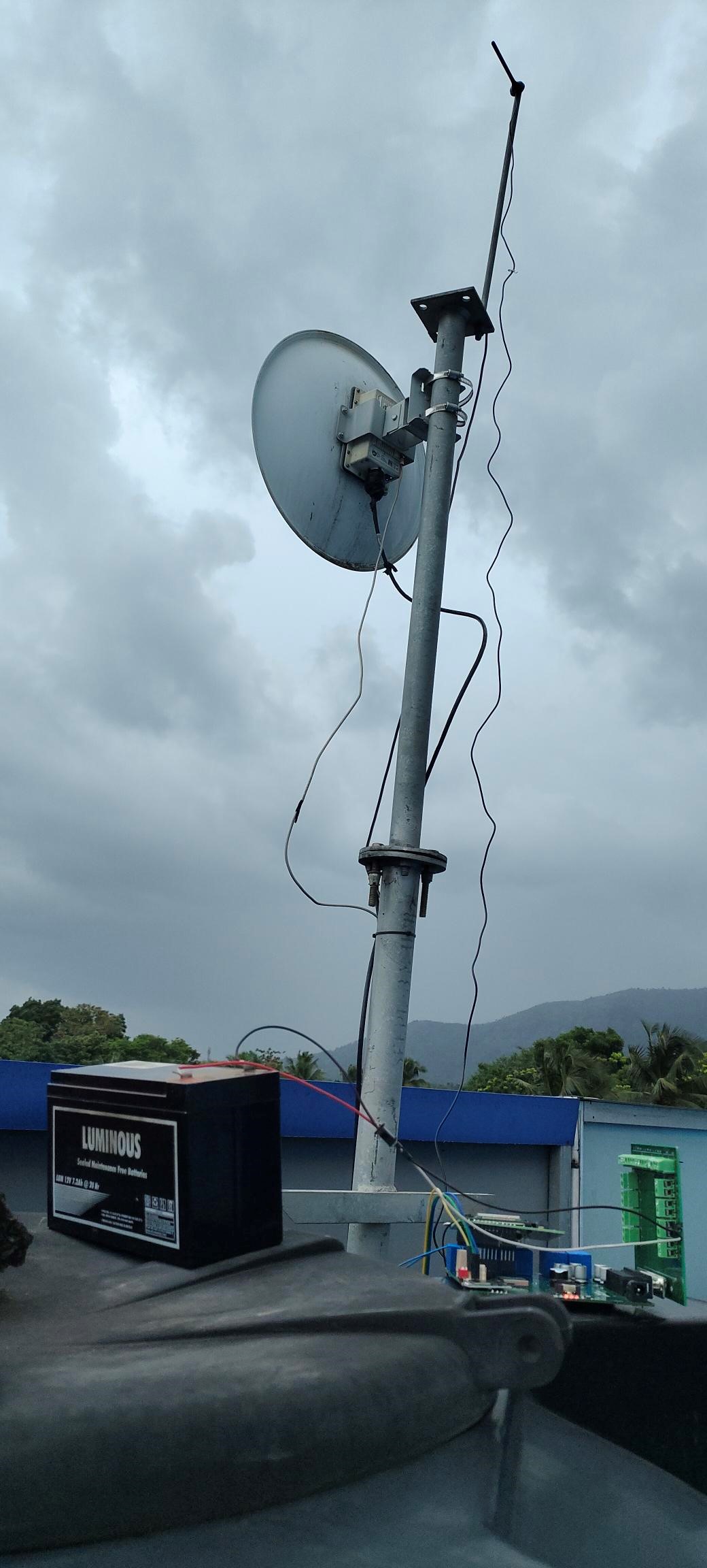
· Antenna Placement: Position antennas at a higher elevation to reduce obstructions and improve line-of-sight communication
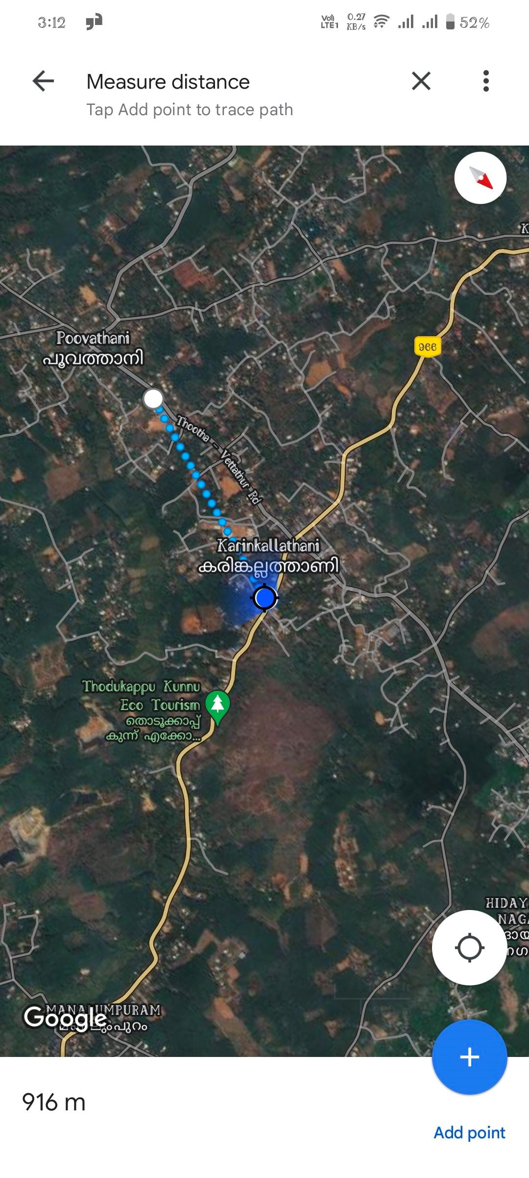
Case1: Inthings technology(Node) to Naduvilathani(Gateway)
· Distance = 916M approximately
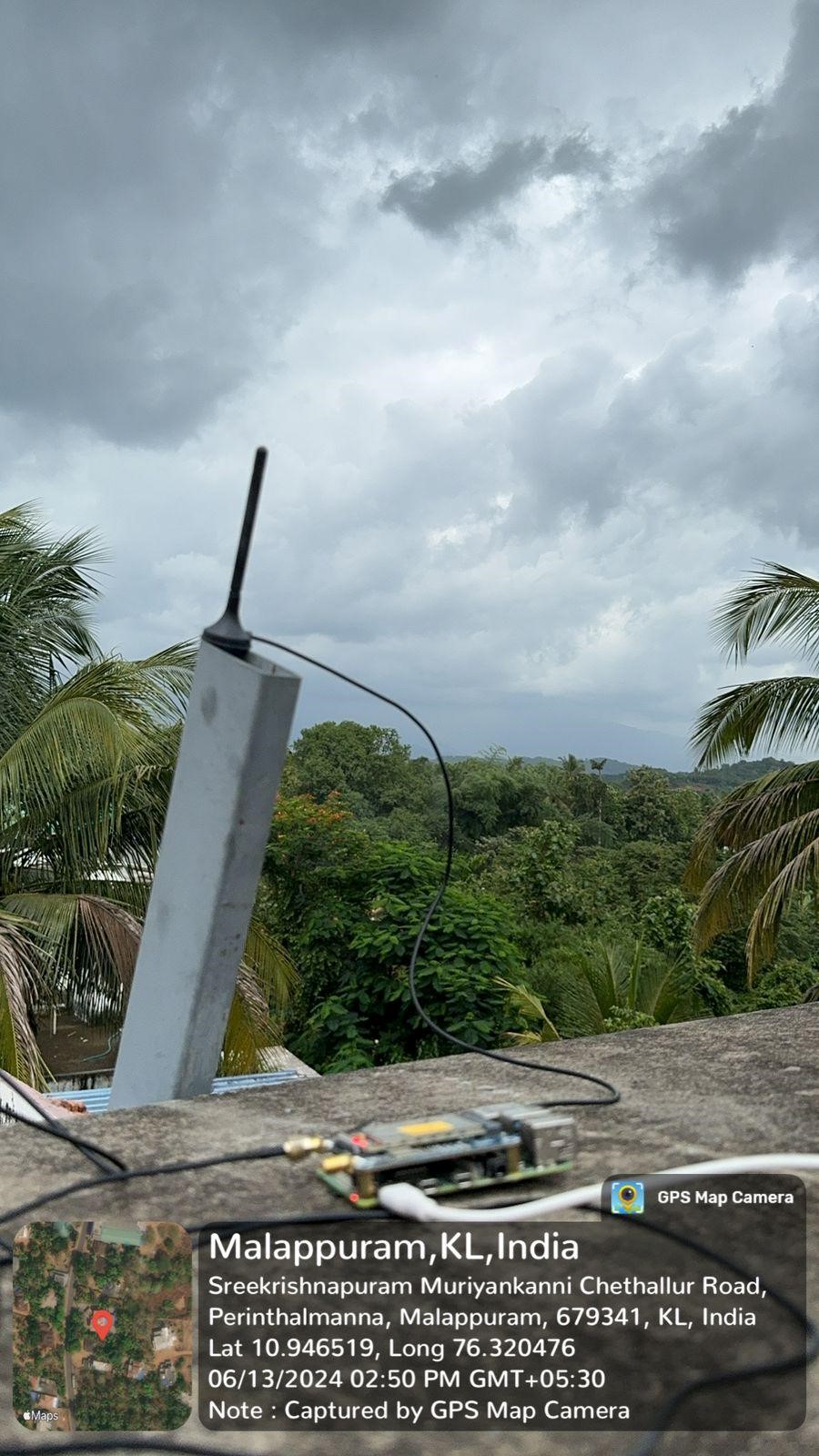
· Antenna used = 5 dBi 915 MHz LPWA Outdoor Waterproof Antenna for both gateway and node.
· Antenna polarization = vertical
· Height of antenna = Node placed on top of inthings building water tank (15M Approx.)
Gateway on top of 2 story building (10M Approx.)
· Line of sight = There are trees obstructing the line of sight between the antenna and the receiver.
· node side antenna should point in direction of gateway because of vertical antenna
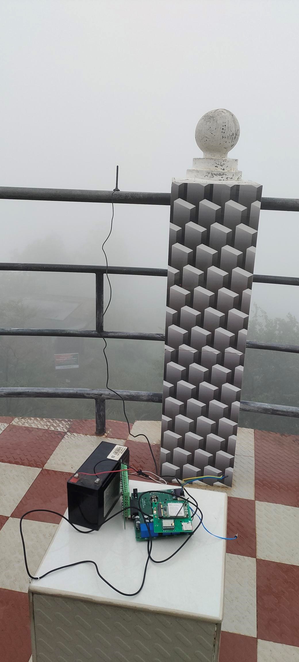
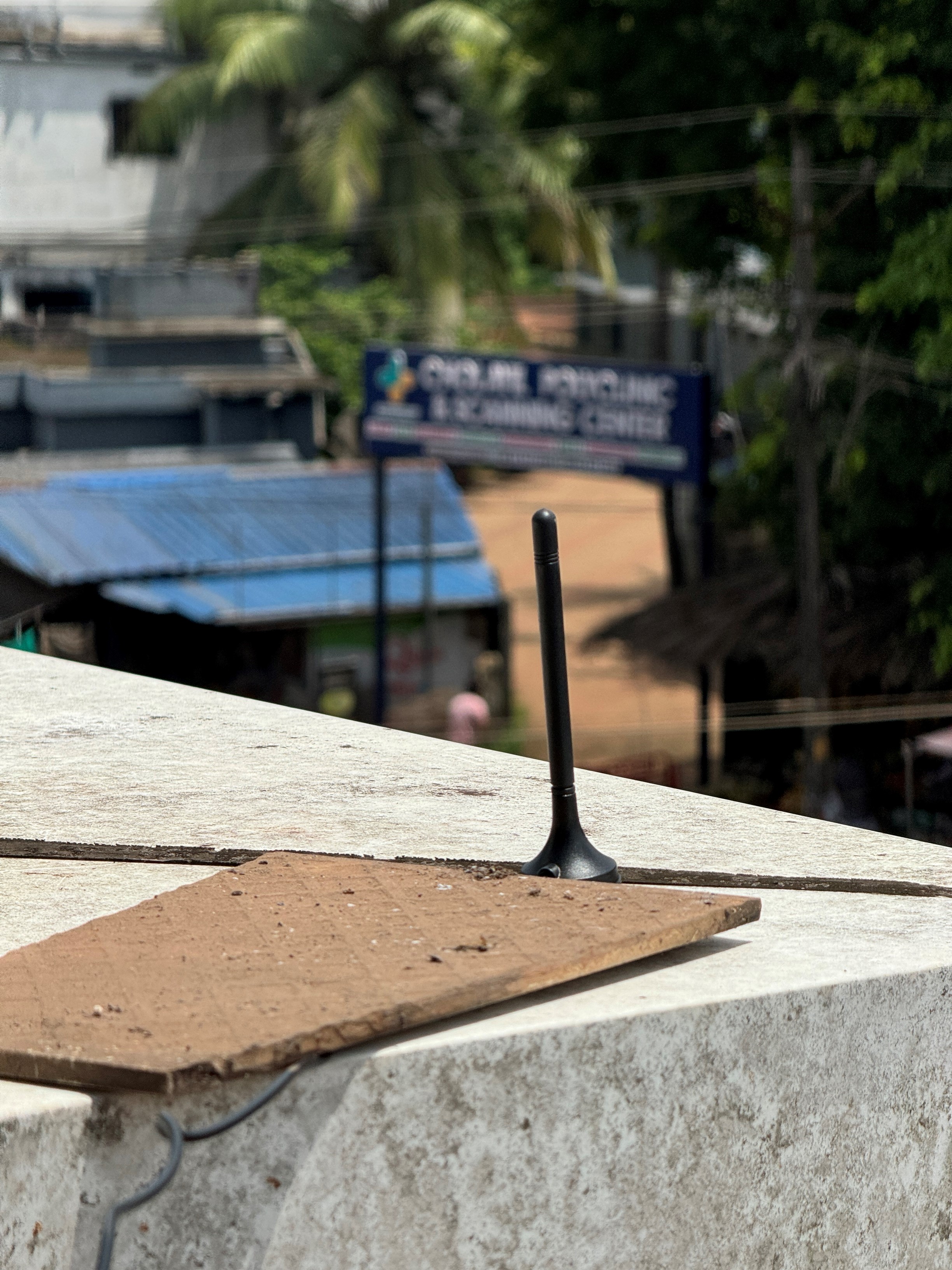
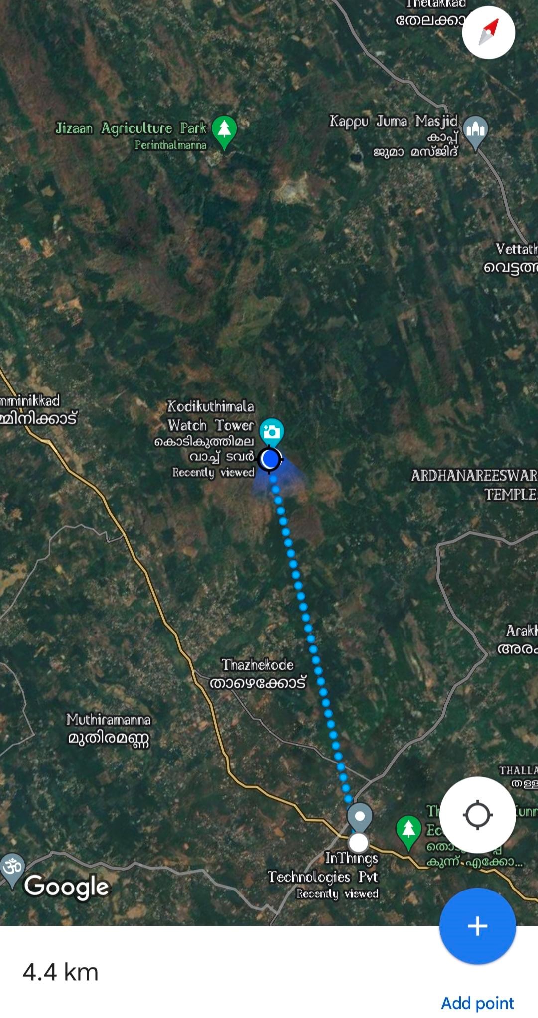
Case2: Inthings technology to Kodikuthimala Watch Tower
· Distance 4.4Km approximately
· Antenna used 5 dBi 915 MHz LPWA Outdoor Waterproof Antenna for both gateway and node.
· Antenna polarization = vertical
· Height of antenna = Node placed on top of Kodikuthimala Watch Tower (540 above sea level) Gateway on top of inthings building 2nd floor (10M Approx.)
· Line of sight = There are no physical obstacles in the line of sight, but atmospheric conditions include clouds and fog.
· node side antenna should point in direction of gateway because of vertical antenna
Outcome:
Conclusion
Replace the current 5 dBi 915 MHz LPWA antenna at the gateway with a 915 MHz Fiberglass Omnidirectional Antenna for better multi-node reception.
For nodes, a 5 dBi dipole antenna is recommended to avoid precise directional alignment. Increasing antenna height (above 10 meters where possible) improves line-of-sight and overall communication performance. Sea level differences should also be considered.
We’ll map solutions to your operations.